Posted on 1 Comment

Metro Made | Sanding Blocks

http://thisisthewilderness.com/portfolio/space/ I watch a lot of YouTube videos. I learn a LOT from them and they often spark a lot of ideas and make my list of ‘things to make’ longer than a giraffe’s necktie. I also subscribe to a lot of amazing youtube creators, a lot of times they are craftspeople who love to share and teach, but do not want the formality of a classroom. I often see interpretations of YouTube projects done by other YouTube creators.

This is a long winded introduction into our next project….the humble sanding block. The sanding block is the eraser of lines, the hider of mistakes, the last touch before going to paint, it is an essential tool with a lot of history. Simply, you can just take a block of any size, usually palm or grip sized and wrap a piece of sand paper around it and go to town. I wanted something a little cooler, a little more custom…a little more…Metro Grade.

So I went off to youtube to seek some inspiration.

I found Gough Custom knives, an Aussie residing in Canada with impressive skills and a workshop I lust after. His uber clean bladecraft is matched by his uber clean shop. In one of his videos, he goes over how he make HIS sanding block, which he uses to sand blade surfaces to sheen.

This was a great design to start from, but I needed to tweak it a bit to make it work for slingcraft. His design uses phenolic counter top material which is water proof because he wet sands his blades. I do not wet sand my projects, so I didn’t need to use that material, plus I have a lot of wood around the shop. I also didn’t want it to have hard, sharp edges, I wanted soft and forgiving because most slingshots are curved and have ample radii for a more comfortable fit. I also wanted to simplify the cutting and fitting of sand papers.

So….here were the list of things I wanted to have in my sanding blocks

1. Use a 1/4 sheet of standard 9″x11″ sheet of sand paper

2. Soft, forgiving sanding surface so it wouldn’t create flat spots

3. Be comfortable for two or handed use.

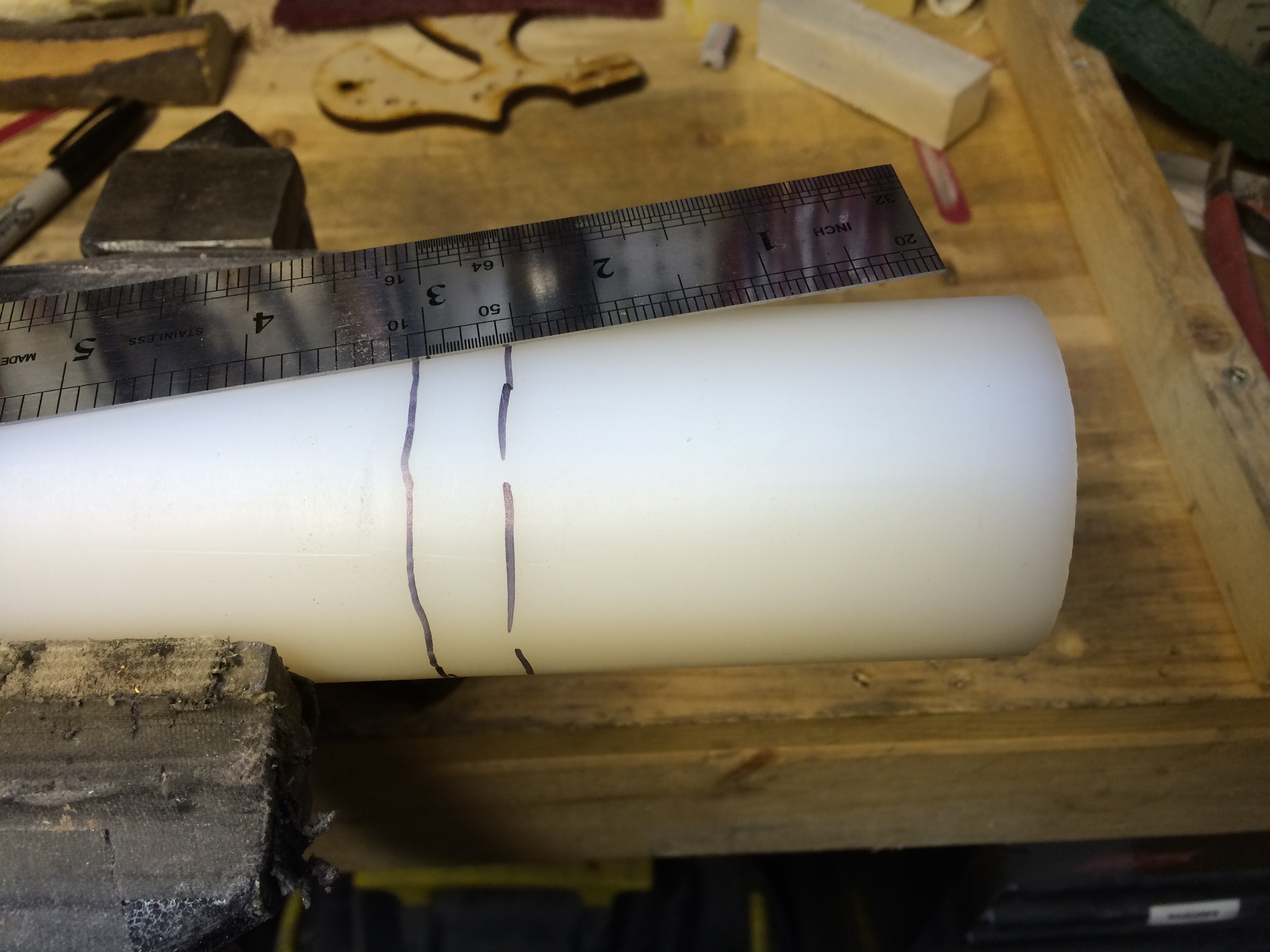
A 1/4 sheet of sand paper measures 4.5″x5.5″ so from that I derived my stock dimensions. I wanted it longer so I went with the 5.5″ dimension. This equated to a 6.5″ long x 1.5″ wide x .75″ thick block. I chose maple because it is a hard wearing material and it machines very well. I made two blocks because contrary to my list of demands for a sanding block, I still wanted one that was hard backed, with one edge square and one edge with a 1/4″ round corner.

IMG_0863

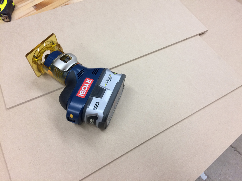
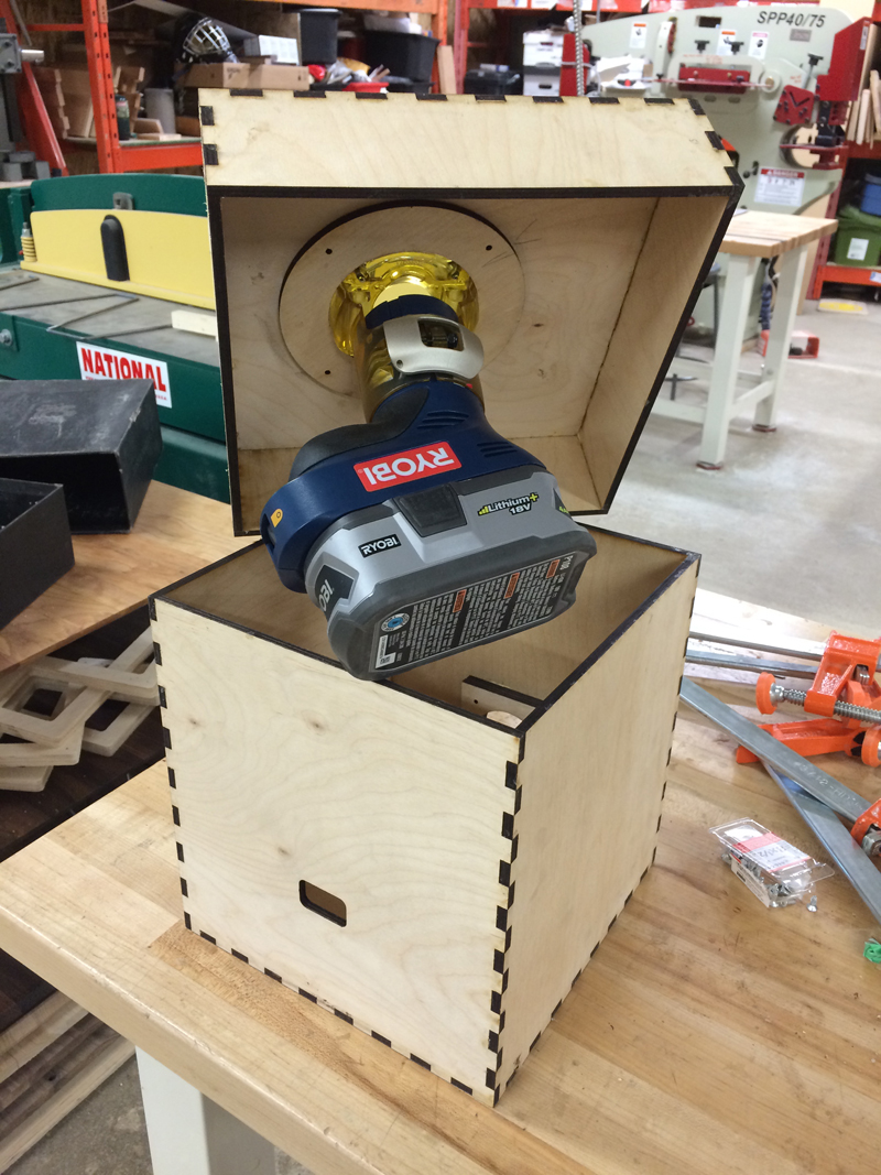
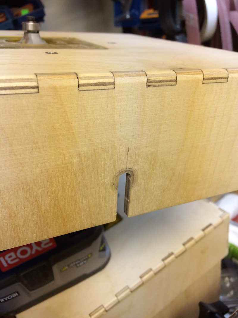
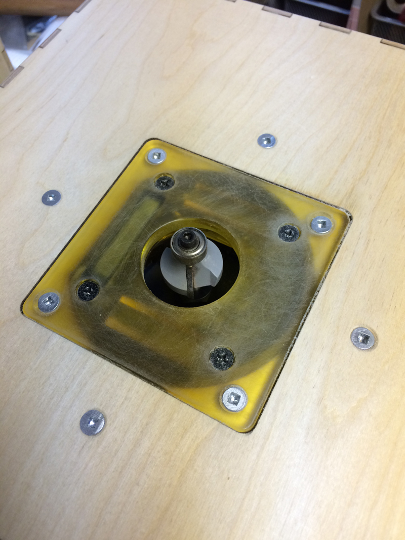
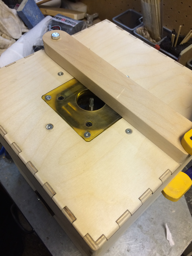
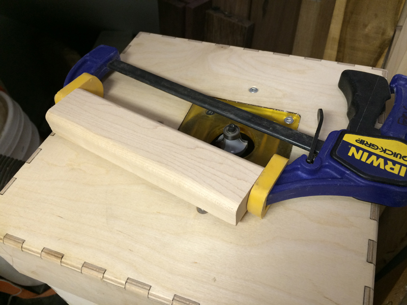
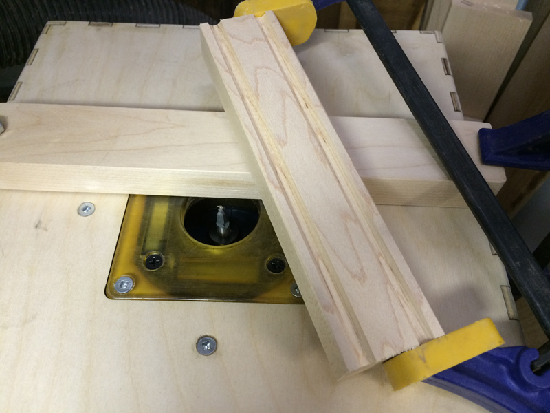
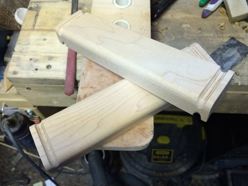
I started to make my block by using my router box with the 1/4″ round over bit. I wanted to try something because as much as I love routers, I also hate them because they are violent machines with GREAT potential for bodily harm. By clamping a quick grip clamp on the piece, I was about to hold onto it MUCH safer and provide better pressure when guiding it against the bearing. I must try this with a sling when the next one comes up. Back to the block, both edges were rounded over, as I mentioned, maple machines very well if you are smooth with your motions and your bit is clean (you should clean it with alcohol and a cotton swap after every job to clear the carbide from resin and gunk).

IMG_0864


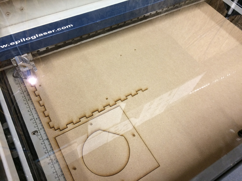
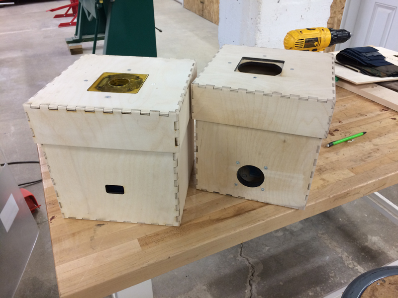
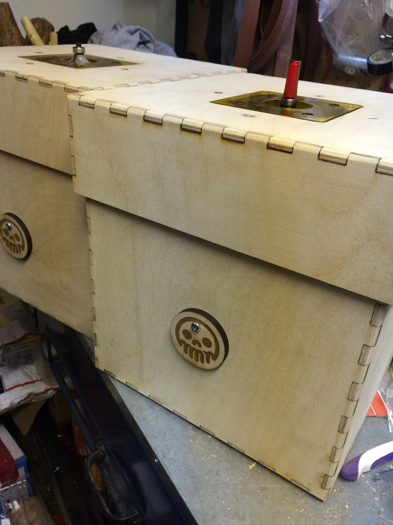
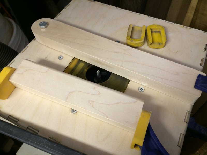
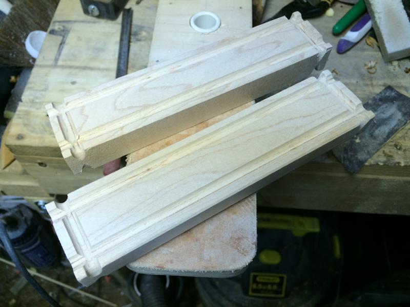
I then switch out the box and move in the other box with a 1/4″ corebox bit in it. The height is set to about 1/8″ depth. The fence is set so the channel created is 1/4″ from the edge. Again, using the quick grip clamp as a extra hand, I ran two slots up the back of the block. This will capture the dowel rods then it comes time for assembly.


IMG_0865

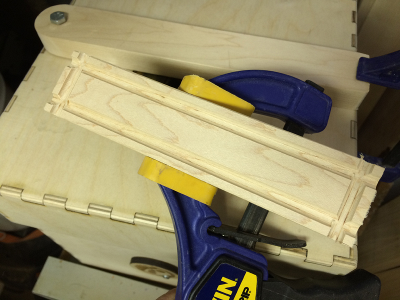
Two identical rails run the length of the block.

IMG_0866

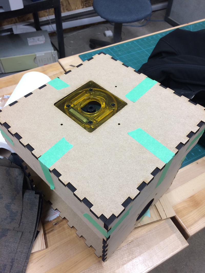
Then changing grips and the fence set the same distance, two smaller channels are run on the ends, both on the top and bottom sides. This will capture the O-ring and hold the dowel rods in place, much like Gough’s design.

IMG_0867

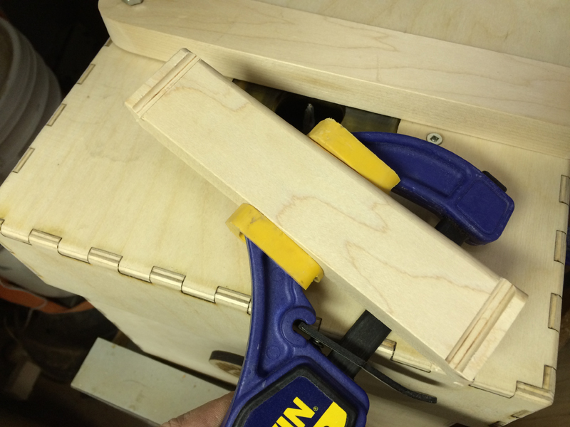
The channels on the top.

IMG_0868

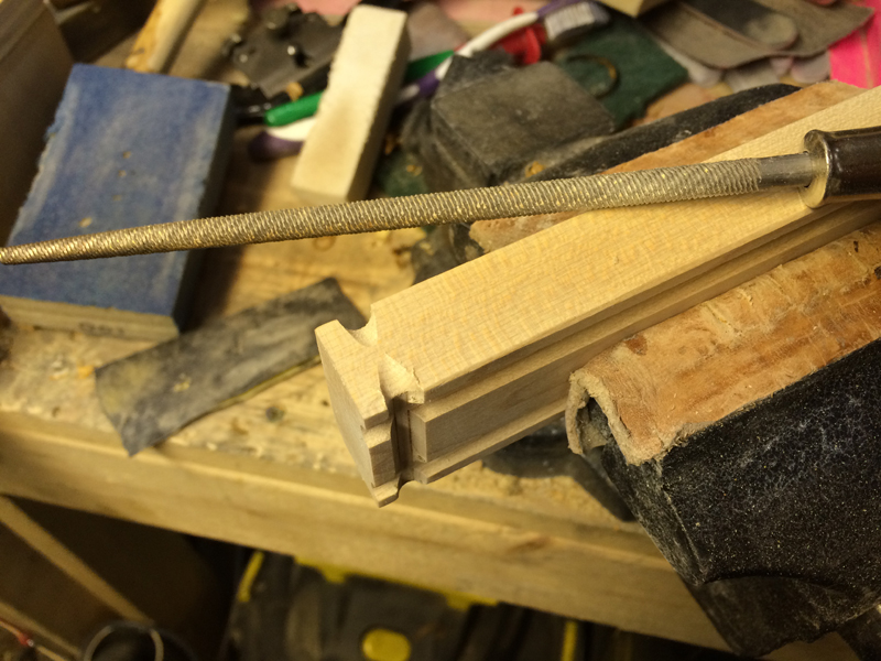
Then it was time for some filing. I could of run the edge into the bit one more time to get a channel, but a skinny edge doesn’t make for a good clean cut. Instead, I used a 1/4″ rasp and rounded out the corners of the channels, transitioning them into the edges. This is much like when I cut band grooves on slingshot fork tips, it was a very family motion for me.

IMG_0869

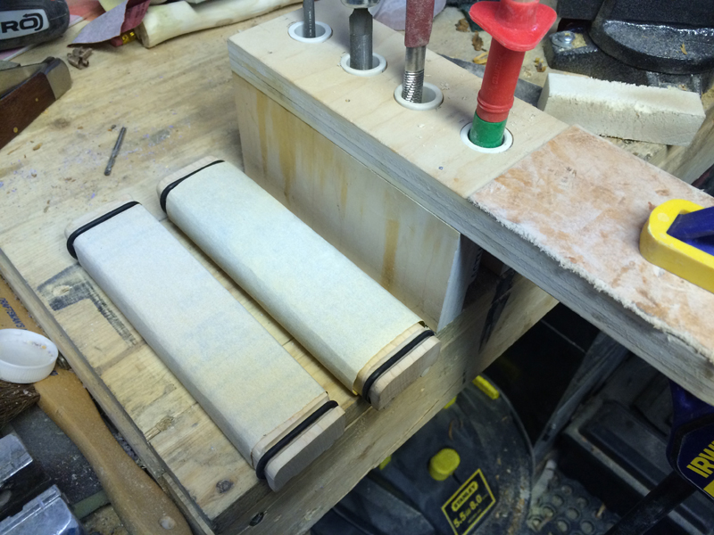
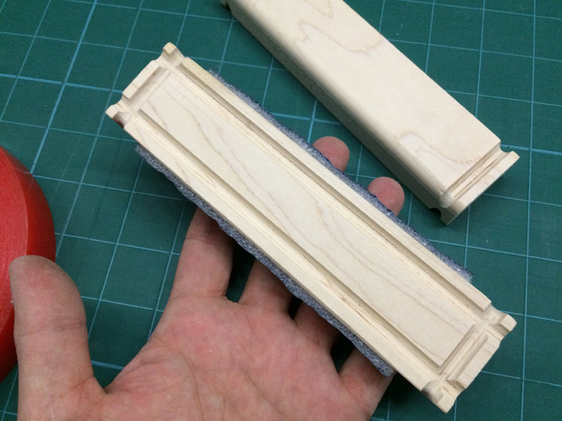
Two completed sanding blocks.

IMG_0870

A little bit of sanding to get rid of the burrs and hairs left from the machining process and it’s off to assembly!

IMG_0871

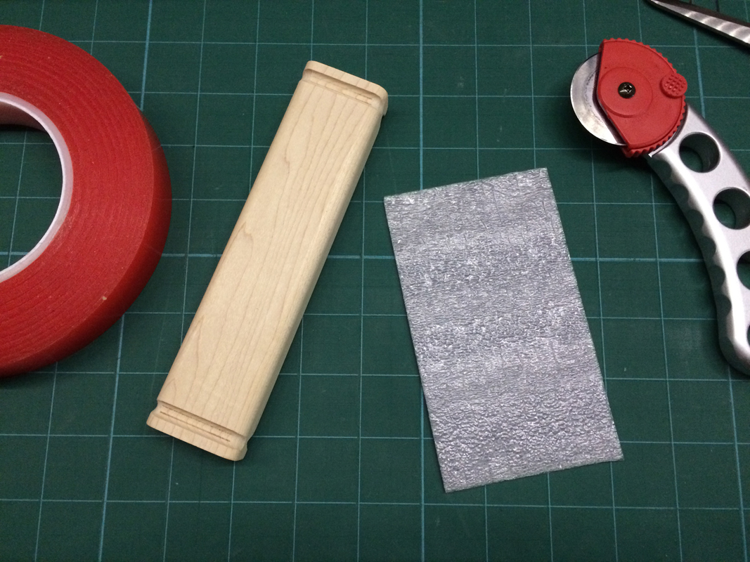
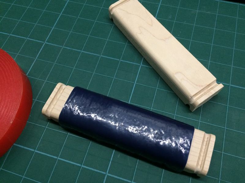
Criteria number 2 was to make the sanding surface soft and forging, like a sand sponge, but without the extra cost of a sanding sponge. To achieve this I needed to pad the surface. I thought I had some craft foam lying around, but I couldn’t find it. You could also use some thin cork but that is less forgiving than foam. I used some left over underlay for hardwood flooring from a renovation years ago. Cut to roughly a 5″x3″ rectangle.

IMG_0872

I backed this with a layer of super sticky 2 sided tape.

IMG_0873


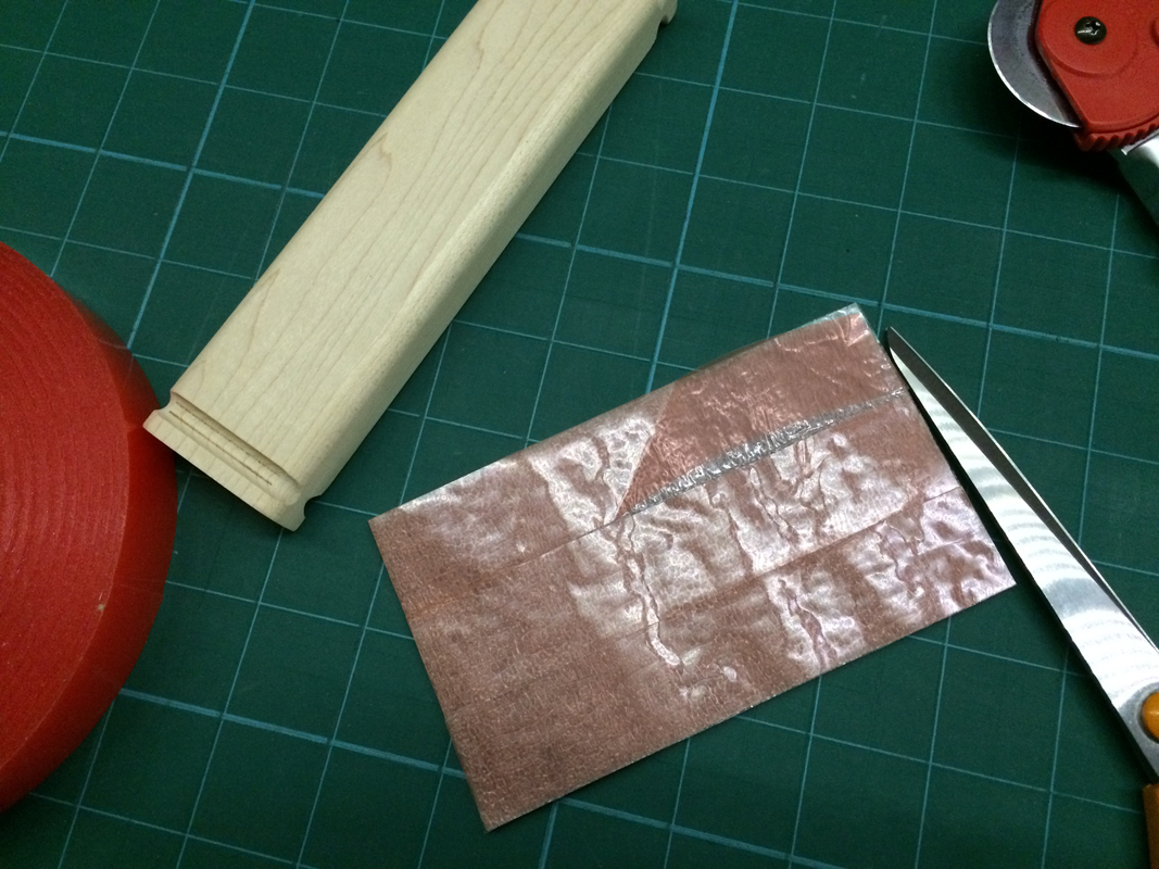
…and rolled it onto place. The other block is left bare, as I mentioned that sometime you DO need a hard backed sanding block.

IMG_0874

IMG_0875

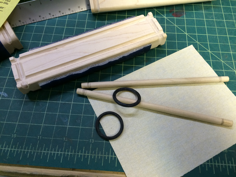
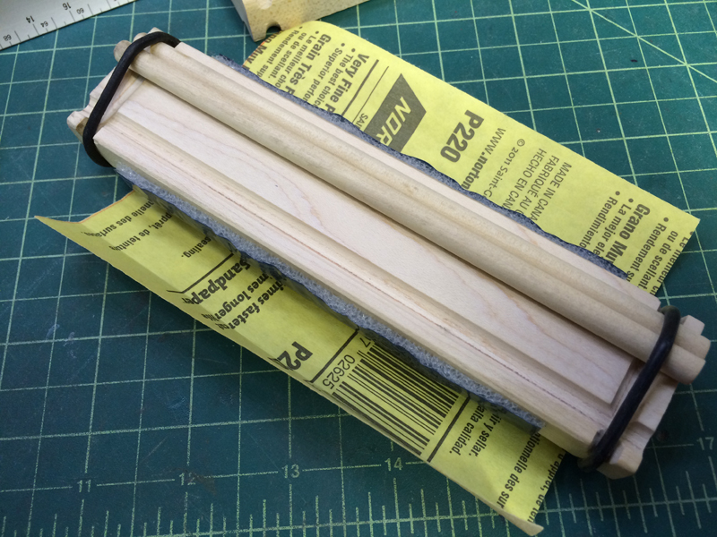
All that was left was to cut some 1/4″ dowels to length. Gough uses some aluminum rods, I usually have some but for some reason or another, I was out! Wood will do for now, they can always be replaced. Two large O-rings also make up the kit, as does the 1/4 sheet of sandpaper.

IMG_0876

Assembly is pretty self explanatory, the rods fit into to channels and the O-rings hold them in place.

IMG_0877

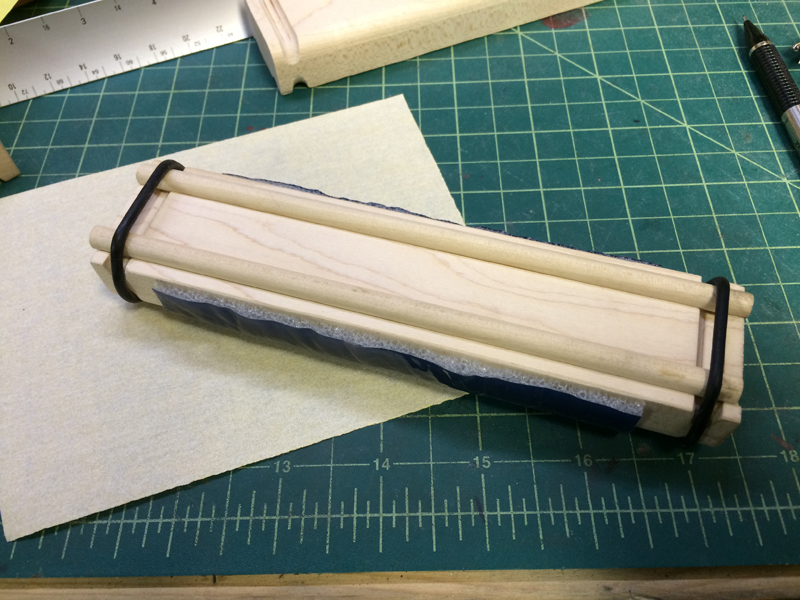
To mount the paper, one rod is moved over and the paper is placed onto the groove, then the dowel is rolled into the groove. No needing to cut the paper into weird sizes.

IMG_0878

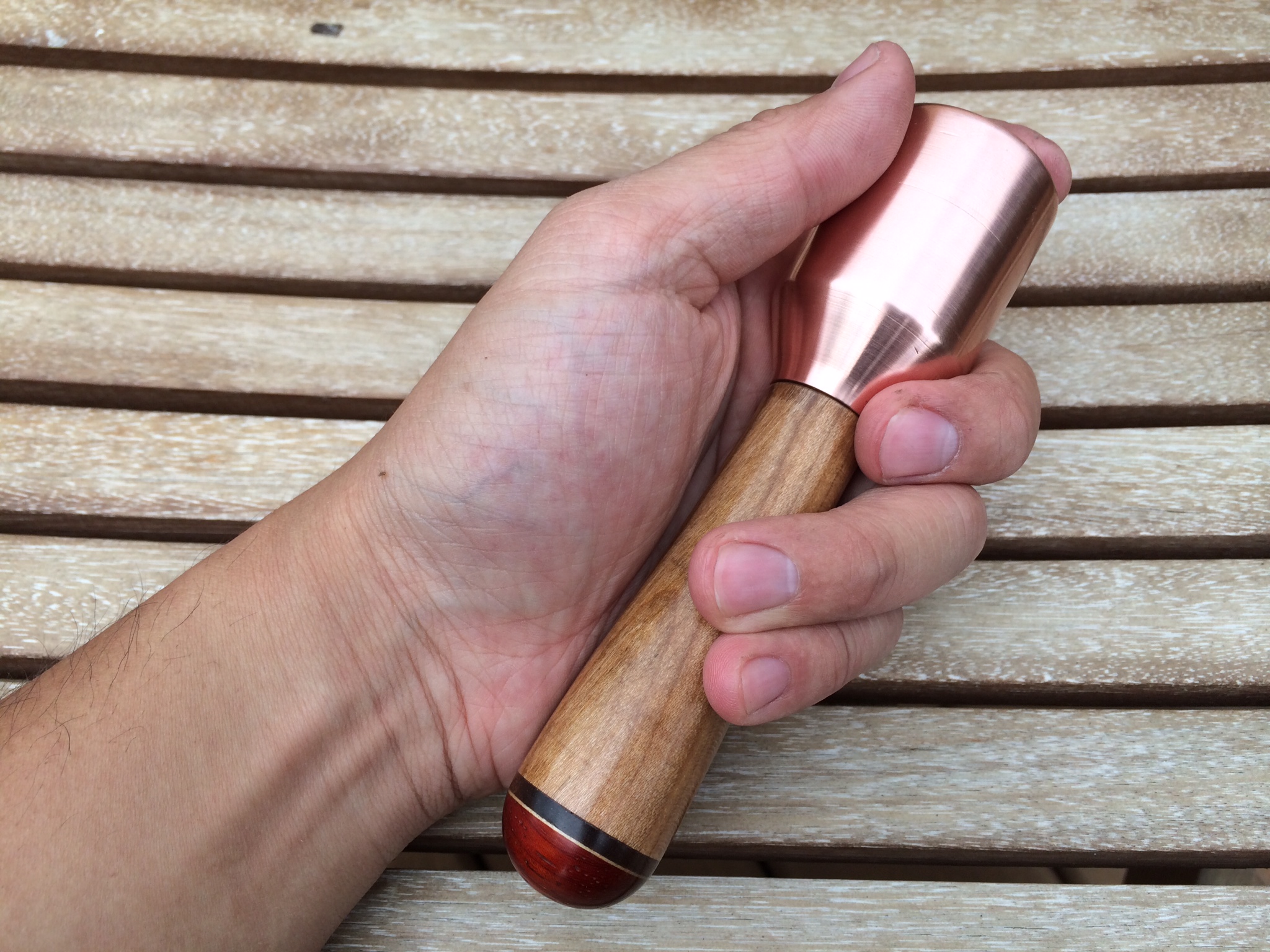
Done. Ready to sand!

IMG_0879

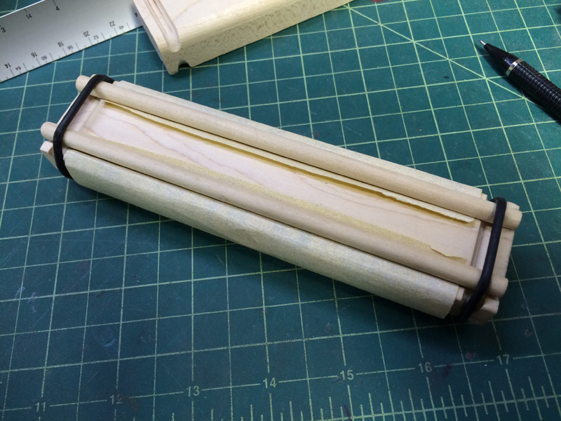
Nice and tidy. The best part about this design is that you have 3 sides and 2 forgiving radii to use for sanding.

IMG_0880


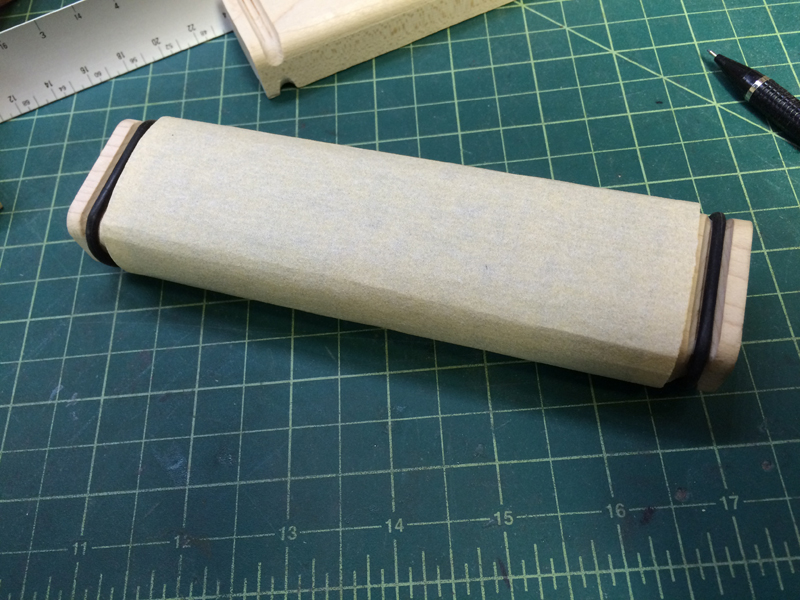
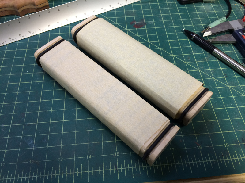
I went ahead and mounted paper on the hard edge one as well.

IMG_0881

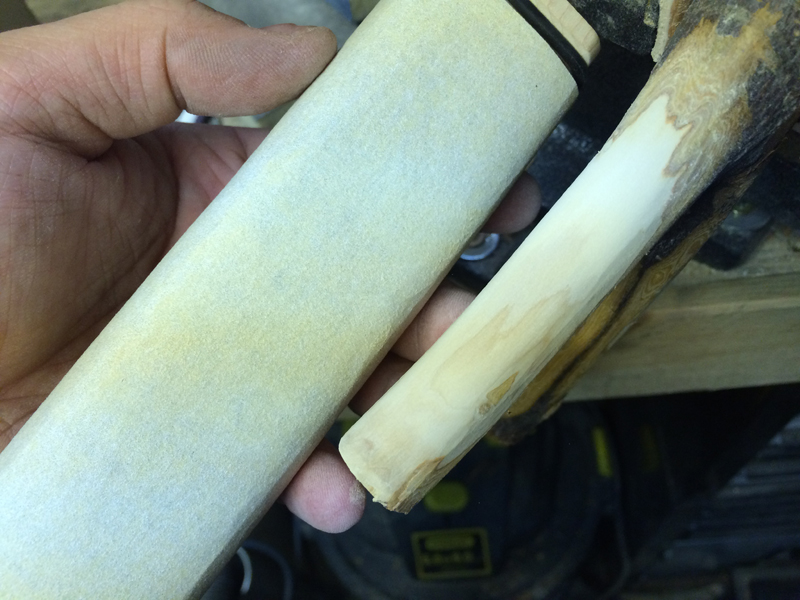
To test out the efficacy of it, I took three strokes with the sanding block on this apple fork.

IMG_0882

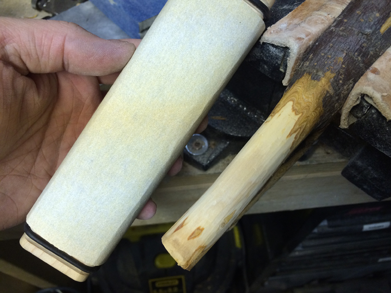
Super smooth and no flat spots (and no premature wear on the paper)

IMG_0883

I really like this design a lot and I think I am going to make a bunch more, for at least an 80, 220, 400 and maybe a 600. I also may make a round dowel version, but that’s for another Metro Made.

IMG_0884

Thanks for reading and I hope you can get something out of this.

Be sure to subscribe to our YouTube channel! Metro Grade Vlog

Happy New Year and have a safe 2015 celebration!

-Eric

Posted on 5 Comments

Metro Made | Mini Router Table Box

excellently More times and not, I enjoy roughing out curves, fillets and chamfers by hand. However, there are times when the might of a router with a proper round over bit is the best ‘route’. When I sought out a small trim router to suit my needs, something amazing came into my sights.

Cruising around the internet, I came across the Ryobi One+ battery powered trim router. At 5A, it’s plenty of power for slingshots and other small projects, and the best part is that it interfaced with my already large collection of Ryobi Li-ion batteries. At $50 a piece, they were inexpensive enough to get a few to save on set up time. I had the idea to build some modular boxes, router boxes, router boxes that would sit on a stand with different tools set up so I could hot swap them out when I needed.

I started by using an online resource for designing finger joint boxes, my plan is to make sorta of a square hat box with the router base sitting on the top. I entered the dimensions into the online box maker and out spit a PDF of the box. After taking the file into Adobe Illustrator, I measured the outside dimension and then generated another box, this would become the lid. I digitally chopped off the top of the base box and then lopped off the bottom section of the lid. This left me with a pattern I could start dropping features onto.

The first thing was to figure out the orientation of the tool. The Ryobi trim router doesn’t have a flat base parallel with the surface of the base, this is meant to be a hand held tool, not stationary. The base didn’t matter, it only means that it would be suspended in the box. This did two things, it allowed for height adjustment of the bit (no need for a complicated lift system) and would also allow for the router base to be level with the box surface without bracing. Measuring the base of the router, it was a 9cm square with about a 3/8″ rounded corner, so that’s what got drawn on the top of the lid. Directly under the layer is another layer that would support the head and also index the router so it would always be in the same position. This is a lot of reading without much photographic explanation but it was such a fast process the later images will make sense after reading this.

The second thing was the on/off switch, being a battery powered unit, the front of the tool needed be accessible so that it could be turned off and on while in the sealed box. So locating the switch and making a generous hole in the front panel of the bottom box was done. A rotating switch plate would cover the hole so increase the dust collection effect of the vacuum…..

Which brings us to the third feature, a dust collection port. On the back panel, a 2.25″ hole was located so that a hose could be attached to have a down draft effect. While a SOME chips may make it away from this vacuum, most will be carried away. Two additional layers of material could be glued to the inside to create a .75″ flange so that hose would have something to grab onto.

Ok….so after this was designed in both my head and in 2D, it was time to prototype in MDF. Throwing a sheet of 1/4″ MDF into the laser, one by one the panels were cut out. On top is the router with the big battery.

IMG_0807

First cuts of the first panels. You can see the plate on the near the bottom of the sheet, it’s the indexing ring and support.

IMG_0806

First dry fit of the parts. The finger joints were actually sized for stock that is .235″ thick and the MDF is .255 so they don’t line up here. Not a big deal since the MDF was just used for sizing and for first fitting.

IMG_0808

The router clears the bottom nicely and will allow for about 3/4″ of travel downwards.

IMG_0809

After editing the files to change a few details for alignment, it was time to move to some Baltic birch. You can see the indexing plate is now round, I forgot to account for the inside edges of the box. Ideally I this would of been made out of 1/2″ plywood, but the laser has trouble cutting that thick of stock. With a 10″x10″ foot print, the box will be plenty stiff.

IMG_0810

Dry fitting the plywood parts. You can see the beginnings of the dust port near the bottom of the box.

IMG_0812

I should note that I made two of these boxes, one for each router, and my 2nd one went 4X faster like with any multiple build. The glue joints on the 2nd one are much tighter, I previously hadn’t worked with so many finger joints at once. I also sanded the edges to get rid of the burning PRIOR to gluing on the 2nd one.

IMG_0813

This is basically it. The rectangular hole on the front is the switch hole, this got lengthened by hand later to adjust for the bit height. The support/indexing plate was glue in place and further reenforced by 4 countersunk screws.

IMG_0814

IMG_0816

A shot of how the router looks like suspended by the support/index plate.

IMG_0815

A quick zip on my other router table to cut the edges down and it was time to make a second one. Next to the first box (on the left) is the second box. Like I said, it was 4X faster to make the second one.

IMG_0817

Once the basic form was made up, it was time to address some performance details. First, the switch hole cover. No Metro Made project is complete without the Metro Grade skull.

IMG_0818

This is simply screwed in place (the hole on the skull plate is bigger to allow for rotation).

IMG_0819

I knew the routers would likely have a lot of vibration and with such a light weight box, it would be amplified. To combat this, two bricks were put inside the box to weight it down and some rubber feet were installed on the bottom to dampen the vibration. This also makes the whole box very sturdy when in use, less fear of it tipping over with the center of mass, well below the table’s surface.

IMG_0820

The best part about these boxes is that they are BOXES! which means they are perfect for storing the adjustment tools. I don’t know about you but I have a small collection of cheap tools, so leaving this small 8mm socket wrench and the bit adjusting wrench ready to be used INSIDE the box is great. Some commonly used bits can also be stored inside the box, I have to make sure they are weighed enough so that they won’t get sucked into the dust collector. This is also a good shot of how the dust port looks like, two additional layers of plywood make up the port.

IMG_0831

To lock the lid down, I used two 1/4-20 bolts with a flower knobs on either side that correspond to two slots cut out of the lid.

IMG_0821

Here are the slots. On the underside of the lid, on the inner corners, a thin 1mm cork strip was glued in place to increase the contact of the lid and the box. This should dampen the vibration more and also make for a better airtight seal.

IMG_0822

The surface of the router plate was TOO slick so some 220 grit sandpaper took off the sheen and added a bit of traction for better control. 4 additional screws were added to the router to really suck down the router base surface to the box lid.

IMG_0823

One final shot of the dust port.

IMG_0824

The first box will be set up with a 1/4″ round over bit almost exclusively so the 2nd box needed a few more details to make it more versatile. Aside from being a flush trim box, it will also be the box I use to cut band groove slots on the tips of slingshots. I have to buy a 1/8″ and a 3/16″ core box bits, but the idea here is that the swinging arm will pivot on one end to increase or decrease the distance from the bit and act as a fence for the slingshot to ride on. The free swinging end gets clamped down by a quick clamp. When I figure out the idea distances to swing it, I’ll make some indexing pins to easily repeat the cut.

IMG_0827

Now to install it in the shop. This whole project was spurred when I found this amazing cabinet at my local Re-Store (Habitat for Humanity) for $15. I think it was used as an mail inbox unit, obviously part of a larger installation due to the unfinished sides, it’s very sturdy. I put some medium duty casters just so I can move it around, but when I am using it, I have it blocked up in the front.

It is the PERFECT thing for organizing my thin woods and smaller blocks of lumber.

IMG_0828

The cabinet had a lip on the top side, which I actually think was the bottom, which is nice for the router box to rest up against. I freed up the area in front of the wood storage by moving the small blocks to the new cabinet. There is just enough space to get behind there and get the larger planks of stock. The modular boxes allow me to move the whole unit off the base and then move the other box into its place, no need to spend time changing bits.

IMG_0829

I know I’ve gone on and on about the dust port but router make such a mess if you don’t control them.

IMG_0830

So to close this Metro Made up, a short video of the first run on the router box. I hadn’t installed it on the base.

To celebrate the finish of these boxes, I made this Blood Orange Tyton with it. The smooth radius courtesy of the 1/4″ round over bit.

MAR_2081 MAR_2083 MAR_2084  MAR_2087

Thanks for reading and have a superb holiday season!


Posted on 1 Comment

Metro Made | The Death Rattle Mallet

In this Metro Made, we set out eyes on yet another tool, the humble leather working mallet. I punch hundred’s of holes each week to slide metal clips into place or buttons snaps. For a long while, I used a simple 10″ long traditional mallet made from nylon.

I wanted something more compact and…of course, custom made for my workflow. I really enjoy using my Copperhead mallet, so much that I wanted a bigger, soft head version for strike leather punches. I call it the Death Rattle…you’ll know why soon enough.

Let’s go!

First, let’s cut the stock for hammer striking head. Some 2.5″ diameter Ultra High Molecular Weight Polyethylene will do the trick, no silly nylon or HDPE, this stuff is the bees knees in terms of weight and durability. A healthy 3.5″ was cut off from the log.

IMG_0020

This stuff was tough, even with my most aggressive wood saw, it took quite a lot of work to make it cut.

IMG_0021

Now time for the real work…the piece was chucked up on the lathe. It JUST fit on the mini lathe. This is the most dangerous step, with the uneven surface of the saw cut face, it could catch the tool and bounce right out of the jaws. I wanted to face the end so as to flip is over to get a better grip on the material.

IMG_0022

After many, many light passes, the first surface is faced and flush.

IMG_0023

Flipping it over, the other side was much safer to face. If my lathe was bigger, this wouldn’t of been such a hassel.

IMG_0024

I managed to buy a bunch of tool handles from Lee Valley tools for a scant price of $.50 each. They came all ready to go with a 5/16 fine thread rod. This is the same handle I used for the Copperhead Mallet, so it may look familiar to you frequent readers. Here I eyeball up how far I need to make the threads.

IMG_0025

UHMWPE may be tough, but it yields to drill bits quite nicely. A fat centerdrill is used to get the hole started.

IMG_0026

Then a 5/16″ was drilled 1″ in. This allowed for the tapered tap to get far enough in to make a nice clean set of threads.

IMG_0027

Test fit and we a basic hammer. I could leave it like that, but where’s the fun in that!?

IMG_0028

Fully seated.

IMG_0029

I then turn a tenon on the so the handle has something visual to sit on. I also face the outside edge, this isn’t needed but it’s nice to have a fresh face to start off with. I don’t show it, but the work was supported by a live center point on the tail stock.

IMG_0030

Then flip is over to finish the facing of the outside surface.

IMG_0031

One fresh surface.

IMG_0032

This was the hardest part of the operation, and this is also why I called this the Death Rattle. The plan is to hollow out the mallet, fill it with steel shot and plug it. I use a 1.25″ Forstner bit to hog out the inner material about 2″ deep.

IMG_0033

Another test fit. I’ll chamfer the end towards the handle for comfort later.

IMG_0034

Time to make the plug. I made a small mistake and used the 1.25″ Forstner bit instead of the 1″, but I found a fix that worked out well. That is a ring of 1″ ID, 1.25″ OD schedule 40 PVC pipe. It’s a near perfect fit and will need to be pressed into place.

IMG_0035

Once I had the spacer, I cut off and machined a bit of 1″ nylon rod to use a s plug.

IMG_0036

The fit was a tiny bit loose, so I wound two wraps of electrical tape onto the nylon lug and hammered/pressed it into place.

IMG_0037

To avoid separation, a 1/32 hole was drilled and counter sunk with a 1/16 bit a small nail was driven into place.

IMG_0038

Chucked the plug with pvc sleeve into the lath again and faced it so it was one unit, then pressed it into the hammer head. The same hole set and nail was driven in to pin it place. The fit was pretty tight to begin with, but this is just for added security.

IMG_0039

I had forgot to mention, the tapped hole was drilled clean through into the now void chamber so that I can pack in the steel shot though it. That way, there was no need to fiddle with the plug and getting the exact amount of shot in it. I can tune it later if needed by removing or adding more steel shot or sand.

IMG_0040

Now to fill it with .177 BBs. A bottle of these are so cheap, they make great ammo AND weights. Slowly but surely, the chamber fills up and there is a tiny rattle sound from the micro voids. Now you get it…it’s called the Death Rattle for a reason.

IMG_0041

Once it was filled up, handle replaced onto it, the feeling wasn’t right. Then I remembered I was going to chamfer the bottom edge. So back on the lathe it went to receive a 30 degree bevel. Now I can choke up on the it if needed. The final weight is just over 10 ounces which makes it a weight to swing and hit a punch without much effort.

IMG_0042


I may revisit the handle and give it a nice end cap detail. I also may add a eye bolt on the end of the handle to hang this up on a peg, but for now, she’s serviceable and ready to smack some tools!

IMG_0043

IMG_0044

IMG_0045

IMG_0047

IMG_0048

Thanks for reading once again and don’t forget…Christmas isn’t that far away.

-Stay True-

-Eric

Posted on Leave a comment

Metro Made | Copperhead Carving Mallet

I have been getting back into tooling mode lately, collecting and acquiring hand tools and finding ways to make them uniquely mine. In this Metro Made, I craft a carving chisel based on a classic brass headed carving mallet.

Lets being by looking at the inspiration…the wood handle. I went to my local Lee Valley tools to pick up a set of Milled-Tool files and I looked over at the discount table. Low and behold, there were boxes upon boxes of discontinued handles. For literally $.25, I could get a full finished, cherry wood handle with a nice 5/16 threaded row already installed into it. I had no idea what I was going to use them for, but I bought them all.

After doing some research into a nice design for my own metal head carving mallet, I came across an archived image from Veritas tools, Lee Valley’s house brand. The same handle appeared, I knew I was on to something.

15K0501s1

Some more research later, I find what I feel would be a good design, I love how the neck of the brass flows into the handle with no transition or break line. I didn’t know if I could get that tight of a fit, but I would try my best. The image is also from Lee Valley’s archives. This is currently sold as the “Journeyman’s Carving Mallet”.

blow_73C67541-5056-9C00-64EFCA02F86EEC24

I didn’t have any 1.5″ brass stock, but I did have some 1.5″ Tellurium Copper. Tellurium Copper is awesome, unlike the 99.9% pure copper, the added alloy of Tellurium makes it machinable and very hard. This is a hunk of it for scale.

IMG_8445

I cut off 2″ from this 12″ rod and chucked it up on the lathe.

IMG_8446

I mixed up the order of operations, in hind sight I should of machined the ‘face’ of the mallet first entirely and then chuck it up again on the otherside. Instead, I faced on side and tapped 5/16 thread into it. The handle already had an attached 5/16 bolt which made this project so much easier to deal with.

IMG_8447

I tapered the head at 30 degrees and took off the cooper until it almost met with the wood. From there, I used a half round file to manually blend the wood and copper till they made the a similar seamless transition. Before I finished the whole handle, I added some end cap detail by laminating some walnut and paduak spaced with maple veneers. Purely decorative, but sure makes it nice and custom.

The handle was then spun and using 80, 120, 240, 400, 600 and some steel tool, I prepped the surface to accept 4 coats of super glue. Having it already on the lathe made applying the super glue finish easy as I spun the handle very slowly. I hit the surface again with the steel wool to even out the glue.

I pulled a painters trick and used some bunched up news paper and turning the handle at it’s fastest speed to buff it to a very even shine. It feels like a pool cue.

IMG_8448

IMG_8449

IMG_8450

The end result is a copperhead carving mallet with a weight of just over 1Lb or 465 grams. Plenty of heft, but thanks to the small handle, incredibly controllable.  IMG_8452

IMG_8453

IMG_8454

I love the end product so much that I want to make a smaller one, maybe 1/2 or 1/3 pound to compliment each other.

Thanks for reading!

-Eric

Posted on Leave a comment

Metro Made | Oak Metbro Unishot and Classic

Since the launch of the new Metbro line, they have garnered a small following of slingers wanting to try out the old school feel but with some modern aesthetics. This Metro Made is about finishing a pair of Metbros, a Classic and a Unishot with some old growth oak, brass pins and a leather insert for the thumb pad.

Want to make one? Check out our Maker category.

Metro Grade Goods Maker Category


Posted on 2 Comments

Metro Made | Pimping the Manfrotto Nano 5001B Lightstand

Since February 2006, the humble blog Strobist fashioned by seasoned media photographer David Hobby, has spawned an army of photographers wielding small off camera strobes, producing stunning and technically challenging imagery.

By using light weight equipment, smart thinking, public discourse, open-source education, and creative and often unconventional light modification sources, the Strobist movement has taught 1000’s of amateurs how to light and convinced professionals that sometimes a 1000Ws studio strobe is the only answer.

The backbone of the Strobist methodology of photography lighting is using ultra lightweight and compact lighting support. While this is the goal of MOST photographers, Strobist or not, David hobby introduced one of the best kept secrets in the photography support catalog, the Manfrotto Nano 5001B (formerly 00B). I am not saying I discovered this secret before, but I also used one of these in my 15 years of professional photography, however mine was a very early model with friction locks and a non-black finished. This baby has been with me literally everywhere, through most of Asia, western Europe (include it’s birthplace, Italy), a whole bunch of the Mid-Western and East Coast of the USA and across Canada. This maybe not be the 5001B with it’s new school cool, but it sure didn’t give up at any moment. I’ve since retired it in favour of the 5001B Nano because I did like the anodized black finish.

ROS_8357

The Nano 5001B is one of the lightest and smallest flash stands on the market with plenty of Chinese variations, and David made a great post about how to hack it into something super portable, quick to deploy and easy to carry. This post is about how I pimped my newer 5001B, which has been around the block already but I recently updated it with a few new video features.

ROS_83581. Leg/Umbrella Management, elastic cord 

Let’s start with the simple, this mod is so simple and so cheap that it is a no brainer. The cost of this mod is maybe, $2 if you go fancy, free if you have some of this stuff lying around the house. One of the few pains the Nano stand has is the legs tend to be a bit floppy when they are closed up. This is due to the geometry of how they fold up, backwards to any other conventional light stand. It accounts for it’s mere 18″ closed length. David uses a ball bungee for this, which does the same thing, but I found that I lost more ball bungees without some kind of retention system. So I came up with this adaptation.  

To manage this is simple, you need:

1. A length of shock cord (can be from a ball bungee)

2. A cord lock that can fit the shock cord through

3. A cord end.

The result is this:

Elastic alone

Pretty simple right? This can taken off and used like ball bungee to tie up strobes or hang up stuff but only when you need it, otherwise, it’ll stay put on the Nano stand. This gets looped onto the tightening handle of the legs, the cord lock is used to cinch up the shock cord and the cord lock on the end is a nice way to finish it off as well as give yourself something to pull on.

elastic without umbrella

In addition to wrangle the legs, the shock cord is also used to hold a full size umbrella onto the closed stand, making this a nice tight package with no movement on parts.

elastic with umbrella

This is how it looks when the shock cord is looped all the way around the stand and then hooked back onto the handle. 

Overall 1 w:o umbrella

2. Shoulder Strap

This is one of those mods that when I saw it, I hit myself in the forehead. Of course, why try and find a bag for something that I will just use as one unit when I can just carry the whole unit as is. David drilled 2 holes into one of the legs and threaded on two keychain splitrings, which gave him two mounting points for a strap to be clipped on. I liked the idea of it but I didn’t like how much noise it made (the clanking).

I used some 1″ D-rings and 1″ gaff tape to attach them to the leg that nests into the split of the upper leg collar. I did this for a few reasons, the split of the leg mounting collar kept the leg from shifting side to side (kind of important if the all the weight is carried on that leg) also the position of the collar and the tightening knobs meant that the only place to store the umbrella was the opposite side of the closed nano stand.

Think I am crazy to think of such a minute detail? When you have 10 minutes to set up, take a photo of the president of a company and breakdown again, it pays to know where things go and have it go smoothly.

The shoulder strap is from some random bag that I don’t use anymore, so it was a perfect choice.

Stand Complete


Stand with Strap

Here’s a closer look of the D-Rings and how it was wrapped on. The tape is fresh since the old tape was looking a little haggered. Bright tape helps others see the black stand on the ground and also if I needed take the strap off if the ground is wet, I don’t need to fumble around in dark situations to find the D-rings.

Loop Detail

3. Monopod Foot Mod

Alright, here’s where my version of the Nano stand system differs from any other. I am finding myself doing more and more video, much to my chagrin and wielding a nearly 6-8 lb camera and keeping it steady is a feat best left to higher beings. While attending a wedding in Hong Kong, I noticed one of the crew documenting the wedding using a curious little monopod foot that looked really good. I asked and he showed me where I could get one. A day later, I had in my hands a Benro ST1 hydraulic universal monopod foot. I had already thought of how I could incorporate this into a Nano stand, knowing the bottom base bracket was solid cast aluminum. I bought the one with the 3/8 thread to get the maximum amount of support.

The Benro ST1 is a mini tripod foot, meaning it has three legs. The Nano stand also has three legs, so I thought I would be able mount the ST1 on the bottom and have the short legs nest in the empty space between the Nano legs. I was right!

I drilled and tapped the bottom of the Nano stand with a 3/8″ thread, ready to accept the ST1. Not going to lie, I misfired and didn’t hit the centre of the base, but it didn’t effect the result much.

Threaded Hole

After mounting the ST1 on the bottom, the effect is as expected. The legs of the ST1 nest PERFECTLY into the legs of the Nano.

Mono Foot Folded

When open, they lock into position and the integrated ball head allows for a smooth freedom of movement on nearly any terrain.

Mono Foot Close up Since legs nest, it will not affect the Nano’s leg extension, even when lowered into its tallest position.

Regular Feet

One of the added advantages of having a second set of smaller legs is that if the bolts are tightened for the ballhead on the ST1, it will stand up on its own. Making this a perfect stand for those places where you can’t deploy the full legs need a super low profile (untouched, indoors) naked flash stand.

Flash Skinny Stand

Which brings us to our final mod, the business end, the flash bracket.

4. Universal Monopod/Flash Bracket Mod

Only wanting to carry a single implement of support, for video work and the very occasional low light situation where I need I monopod, I needed to make sure the flash bracket end was modular. I’ve been using the Arca-Swiss style tripod mounting system ever since I saw Kirk Enterprises and Really Right Stuff and their amazing camera L-brackets which allow for the camera to be mounted in the vertical position without tipping the camera over on its side on a tripod, super unique and useful. As such, the system is a little pricey, but have been adopted by many manufactures reduced the initial cost of moving to that style of mount.

I started with looking for a compact flash/umbrella bracket, having used dozens of kinds, the Manfrotto one is the best. Unfortunately, the Manfrotto umbrella bracket comes with a huge flaw: its size; it’s huge. Way over scaled and overkill for the smaller flash units that I use. Many eBay searches later, I found one that not only appropriately scaled, the tilting mechanism for the flash/umbrella is index with 5 degree movements, making it impossible for it to slip down or up, its locked in and sturdy.

From there I applied a quick release Arca-Swiss tripod mount on top where the flash would go and a matching plate, I screw in a cold shoe for a flash to sit. More times than not, this is its home state. The flash or PocketWizard TT5 will mount on this, an umbrella is slid into the mounting hole we are off to the races.

Flash Plain

Flash with tt5

When I need to use the monopod features of stand, I simple remove the plate with the cold shoe…

Flash Remove

Slide the camera into the Arca-Swiss mount…

Camera mounted


Close up the Nano legs, open up the ST1 legs…

Camera attach

Camera laying down

Adjust the height for my standing height (shown here at its lowest position), and we are ready to shoot!

Camera mounted standing

The only major mod  that I’ve shown here is the drilling and tapping of the 3/8″ thread in the bottom of the Nano stand, the rest is just careful and considered applications of readily available parts. I hope this was informative and will inspire you to reduce the amount of time spent on setting up equipment and start shooting more!

I can’t wait to get this thing dirty! 

-Stay True-

-Eric


Posted on 1 Comment

Metro Made | The Delta Marker

In my day to day, I carry a pen and a Sharpie marker. I don’t remember when I started doing this but as soon as I wake up in the morning and get my day started at the shop, I always put those two things my my left pocket. I feel weird not having them and they really make up the core of my EDC items.

My most recent acquisition is the beautifully made titanium version of Jason Hui’s Alpha pen, which was a successfully funded Kickstarter project. Jason’s an insanely crafty guy, designing and manufacturing flashlights under his moniker, Darksucks. His low volume, high quality produces ooze style and class for the discerning gear guy/girl. His Alpha pen uses the finest of refills, the Mont Blanc felt tipped fine liner. At $4-5 each, the pen matches the pricey and beautifully writing capabilities of the refill.

Having a medium size collection of higher end custom pens, one of my greatest wishes was for someone to make a beautiful Sharpie marker holder. I’ve been waiting for someone on Kickstarter or other crowdfunding platform to make one, but no one seems to want to take up the challenge. Sharpie does make a stainless steel marker but the design leaves so much to desire and the refilled are fairly expensive given the relative short lifespan of a marker.

I finally broke down and spent some time in front of my lathe and made one. This is turned entirely from 5/8″, 6160 aluminum bar stock and using very commonly sized imperial HSS drill bits. The clip is from a Sanrenmu knife that seats itself into a flat spot milled into the face of the cap.

MGG Delta Marker Plans

Delta Marker internals

Basically, it’s a sleeve that accepts the grip, tip and ink well sponge of a regular sized Sharpie fine tipped marker. Extracting this is pretty easy, just bend the plastic body of the maker till the body separates from the grip. Then slide it into the Delta body and press down with the plastic cap. This seats the “refill” fully into the new home.

I call it the Delta Marker.

Delta Marker carbon 2

Delta Marker carbon 1


Why Delta?

Well, it’s no match for The Alpha pen, and it’s not refined enough to be a Beta so, it’s the Delta marker. It is also based off of Jason’s design, using his cap posting design ad well as the capping design, so it’s only natural to follow his naming convention. The only thing missing is the shallow scallops on the body, to do this I would need a round insert holder, which I broke some time ago.

I also wanted it to seal, so I added a groove at the base of each 1/2 fine thread for an o-ring. This did two things, it won’t allow the nib from drying out, but it also engages the cap when torqued on a bit so it won’t accidentally come apart in my pants or shirt pocket. I actually came about this epiphany when the Alpha pen came apart in my pocket a few times, so I put a few, really small o-rings meant for a AAA flashlight seated at the base of each thread. Lucky for me, Jason designed a relief for the threads, which meant there was a groove for the o-rings to seat. Mine are much less precise, but they don’t need to be since the o-rings I used are much thicker to generate a better seal.

Just a quick note, these are not for sale, it was a personal challenge and this blog is a place for me to present final, in progress, experimental as well as failed projects. It’s not often something comes together so nicely on the first try, but thanks to Jason’s design, a lot of the guess work is done for me.

Here are some table top shots, under the Delta Marker is the Alpha pen.

Delta Marker alpha pen1

Delta Marker alpah pen 2

Delta Marker cap

Thanks for making it all the way to end of another long winded, designer rage fuelled build. I am really happy with the Delta Marker and it will serve me well until I can get this design in CAD and possible CNC this.

-Eric